Theory
The Wheatstone Bridge is an instrument designed for measuring an unknown resistance by comparing it with a known, or standard resistor.
R1, R2, and R3 are resistors of known resistance and the resistance of R2 is adjustable. The resistance R2 is adjusted until the bridge is "balanced" and no current flows through the galvanometer VG. At this point, the potential difference between the two midpoints (B and D) will be zero. Therefore the ratio of the two resistances in the known leg (R2/R1) is equal to the ratio of the two resistances in the unknown leg (Rx/R3). If the bridge is unbalanced, the direction of the current indicates whether R2 is too high or too low.
At the point of balance,

Detecting zero current with a galvanometer can be done to extremely high precision. Therefore, if R1, R2, and R3 are known to high precision, then Rx can be measured to high precision. Very small changes in Rx disrupt the balance and are readily detected.
Alternatively, if R1, R2, and R3 are known, but R2 is not adjustable, the voltage difference across or current flow through the meter can be used to calculate the value of Rx, using Kirchhoff's circuit laws. This setup is frequently used in strain gauge and resistance thermometer measurements, as it is usually faster to read a voltage level off a meter than to adjust a resistance to zero the voltage.
It may be shown by experiment that the electrical resistance of a wire is directly proportional to its length and inversely proportional to its cross-sectional area. The resistivity ρ is then defined by the equation
R = ρL/A
Laboratary Procedure
- Use the Resistor Color Code in the introduction of this manual to determine the nominal resistances and tolerances of all resistors on the resistor board. If the bands are too worn to be seen clearly, obtain a magnifying lens from the instructor.
- Refer to the semi-pictorial diagram in section IV. The letters A-D refer to the same points as in the schematic diagram. Connect resistor A on the board of resistors, the first "unknown" resistor, between bars A and B. Connect the plug resistance box, the standard resistor, between bars B and C. Connect the left end of the one-meter wire to bar A and the right end to bar C.
- Clean the contacts of the switch with a piece of emery cloth. Connect one terminal of the switch to bar C; connect the other terminal to either terminal of the cell. Connect the other terminal of the cell to bar A. Leave the switch open.
- See if any of the buttons of the galvanometer is stuck in the depressed position; if so, rotate it to release it. Connect one terminal of the galvanometer to bar B; connect the other terminal to the long bar D.
- Set the plug resistance box to a resistance of the same order of magnitude as the unknown resistor, by removing enough plugs to total the desired resistance; then twist and push in all of the remaining plugs.
- Close the switch S1. Place the sliding contact near the left end of the wire, and hold one end of it down. Depress the left button of the galvanometer and observe which way the needle deflects. In the rest of this experiment, whenever the needle deflects in this direction, you will know that the slider is too far to the left for balance.
- Move the slider to a point near the middle of the wire. Hold one end of the slider down, and momentarily depress the left button of the galvanometer. Observing the direction of the deflection, and remembering the results of step 6, move the slider to a new position and repeat the test. (Do not move the slider while holding it down, as that would scrape bits of metal off of the wire and result in a non-uniform cross-section. This will lead to the failure of the ratio of R3 to R4 to equal the ratio of L3 to L4.) When the galvanometer deflection has been reduced to zero for the left button of the galvanometer, use the middle button and, finally, to the right button. When there is no deflection, using the right button of the galvanometer, the bridge has been balanced. Record the nominal value of the resistance, the slide wire position (L3), and the standard resistance (R2).
- Set the value of unknown resistor (default will be set as 20 ohm) and click set button.
- Turn on the circuit.
- Now set the values of R1 and R2 using slider.
- Now change the value of R3 until the galvanometer deflection tends to zero.
- Click the simulate button.
- (Optional) Click on Add Observation to add current readings in table.
Set Unknown Resistance
(0 to 1000 Ω)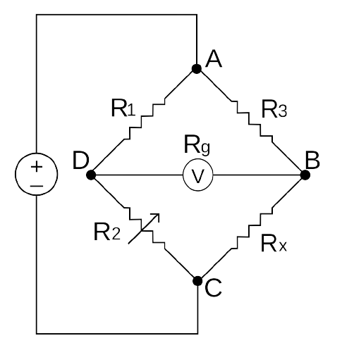

Controls
(0 to 1000 Ω)| Sr No. | V (in volts) | R1 (in Ω) | R2 (in Ω) | R3 (in Ω) | Rx (in Ω) |
|---|
Take a small quiz
About Us
Created by:
| Aditya Ray | 20117006 |
| Lakshman Mulchandani | 20117048 |
| Piyush Thakare | 20117104 |
| Alim Khan | 20117013 |
| Aditya Ghidora | 20117005 |
| Premchand Maddikuntla | 20117051 |
Under supervision of:
Dr. Dhanavath Suresh sir
Department of Electrical Engineering
National Institute of Technology, Raipur